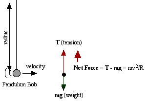
Figure 1.
A swinging pendulum follows a path that is circular in shape. In order to maintain this path, an unbalanced force towards the center of the path, a centripetal force, must be acting. The size of this net force is mv2/R, where m is the mass of the pendulum bob (assuming a massless string), v is the speed or velocity and R is the radius.A pendulum bob has two primary forces acting on it. One is the constant downward force of gravity, mg. The second is tension in the string which changes in both size and direction as the pendulum swings. When it swings through the bottom of its arc, the pendulum has maximum speed and requires the maximum force to hold it in its circular path.
The forces at the bottom are shown here in a free-body diagram. The two forces at the bottom are co-linear, with the upward tension force T being larger than the downward weight, mg, by the required centripetal force. In your experiment, you will compare the measured tension force with one calculated based on the motion.
Figure 1.
Position a motion detector as shown below to measure the speed of the pendulum bob throughout its swing. Careful measurements need to be made of the radius and mass.. The tension force of the support string is transmitted to the force sensor by the pulley and can be recorded by the interface and cpu.

Figure 2.
Note that the length of the string changes slightly as the pendulum swings due to the curve of the pulley sheave. The radius you need to carefully measure is the when the pendulum is hanging vertically. As the length of the string gets longer, or as the pulley gets smaller, or as the arc of the swing gets smaller, the changes in length will become smaller during the course of an individual swing.Preparation
- Set up the physical arrangement shown above in Figure 2. If you use older (blue) motion detectors, be sure to set the lowest point of the pendulum's motion outside the 50-cm minimum distance. Clamping the force sensor to a ring stand will help maintain a constant radius as well as provide a consistent angle during the data run.
- Set up a file for Motion Detector and Force Sensor. Collect data at 20-30 samples per second and a long enough sampling time to capture 3-4 complete swings of the pendulum. Set up graphs for velocity vs. time and force vs. time.
- Calibrate the force sensor in the position that it will be used. If you are using it as shown, hold it with nothing attached and record it as zero (0) force. Then hang a 500-gram mass on the string going over the pulley and record it's force as 4.9 N. Use the Calibrate routine under Experiment in Logger Pro.
- Record both the length of the string and the mass of the pendulum.
Procedure
- Swing the pendulum and record a run of 3-4 complete swings of its motion. Go to the Analysis section.
- Change variables of the experiment and repeat. Some variables might be a) length of the arc the pendulum swings through, b) length of the string, and 3) mass of the pendulum bob. Re-calibrate the force sensor each time for maximum accuracy.
Analysis
- Click and drag over the resulting velocity vs. time graph and then obtain Statistics. From the data that appear, what is the maximum speed of the pendulum bob? Record this value.
- Click and drag across the force vs. time graph, then obtain Statistics. What is the maximum force acting on the pendulum bob during its swing? Record this value.
- Use the maximum speed to complete this calculation:
Calculated Maximum Force = m vmax2 / R + mg
- Compare the value you calculated above to the maximum foce you measured previously by calculating the percentage difference. How well does theory fit your experimental data?
Data Table
Run
1 2 3 4 Pendulum Mass
Pendulum Length
Maximum Speed
Maximum Force
Calculated Maximum
Percentage Difference